Thursday, May 31, 2012

Combining measurements from the L3G4200D Gyroscope and the MicroMag3 Magnetometer using a Kalman Filter

Next up, I wanted to figure out how to combine the gyroscope and compass to provide a filtered estimate of heading. I did a little web searching and came up with a few relevant places with code:
  1. http://www.jayconsystems.com/forum/viewtopic.php?f=22&t=40
  2. http://nxttime.wordpress.com/2010/10/06/robotc-code-for-the-kalman-filter/
  3. http://stackoverflow.com/questions/6013319/kalman-filter-with-complete-data-set
As a reminder, here is a plot showing the measurements we obtained from the two sensors in the last post on this topic.
which shows the accumulated drift error as well as the noise due to erroneous compass measurements. First, I though I would try just a simple combination approach. We know that the integration of the gyro has less noise but drifts. So at each location we predict what the value of the compass setting should be given the previous setting. If the compass disagrees too much, use the gyroscope solution instead. In other words:
predicted = heading(i-1) + gyro(i) * dt;
difference = abs(predicted - compass(i));
if (difference < X)
  heading(i) = compass(i);
else
  heading(i) = predicted;
endif
There is a sensitivity parameter X that needs to be set based on how much discrepancy between the two sensors is allowed say the compass reading should be rejected. This is not much code so it should run fast on the Arduino. In matlab, here are the results using this approach.
This removed the sharp spikes and got rid of the drift, but there is not much smoothing (the values are still jumping around).  To add some smoothing to the result, we can add an IIR filter on top of the selected result. This is accomplished by simply blending the current estimate with the previous.

predicted = heading(i-1) + gyro(i) * dt;
difference = abs(predicted - compass(i));
if (difference < X)
  heading(i) = 0.1 * compass(i) + 0.9 * heading(i-1);
else
  heading(i) = 0.1 * predicted + 0.9 * heading(i-1);
endif
This smoothing result can be seen in the below figure.
This introduces a slight lag when sharp changes are made and the extremes are also removed (when the servo started spinning in the other direction). Again, this approach is reasonably fast with 8 operations and a branch statement. However, it is somewhat ad hoc. 

A better solution might be a Kalman filter. The Kalman filter will incrementally add in new measurement data but automatically learn the gain term (the blending factor picked as 0.1 in the previous example) and allow a more intuitive setting of a noise model. Using the code given at http://nxttime.wordpress.com/2010/10/06/robotc-code-for-the-kalman-filter/, I get the following result.

This approach used a Kalman filter on the compass parameter and only used the gyroscope to detect when the compass gave an erroneous measurement. The Kalman filter also tracks the covariance estimate in how well the prediction matched the new measurements and the Kalman gain. The gain converged to 0.5549 meaning it would average the prediction and the new measurement.

This approach is somewhat limited based on how it is filtering just a single measurement (the compass) and not modeling the dynamics associated with the gyroscope. I did some more searching and found a few good discussions:

  1. http://arduino.cc/forum/index.php?topic=87850.0
  2. http://arduino.cc/forum/index.php/topic,58048.0.html
  3. https://github.com/TKJElectronics/Example-Sketch-for-IMU-including-Kalman-filter
I decided to next try out the code on the last link. This combines the gyro and the compass directly within the filter. I had to adjust several of the smoothing parameters to get a good result. I should probably estimate the process and noise covariance directly from sensor measurements, but first I wanted to get all the measurements going into the filter and determine if the Kalman filter is worth the effort and computation (everything is now running in matlab). Here is the result:

Just based on these plots, it is very difficult to determine the best filtering approach. The next steps are to add in the accelerometer into the mix and look at combining heading information from all three sensors. That will involve using the Kalman filter to weight two measures of heading angle (the accelerometer and the magnetometer).

The code to make all of these plots is on the github site in the matlab directory:

https://github.com/mark-r-stevens/Ardadv/tree/master/matlab


Sunday, May 20, 2012

SPI sharing for using the L3G4200D Gyroscope and the MicroMag3 Magnetometer with the Arduino

Next, I decided to compare the output of the magnetometer and the gyroscope. In reading they both use the SPI interface. But according to this link http://arduino.cc/en/Reference/SPI:
Slave Select pin - the pin on each device that the master can use to enable and disable specific devices. When a device's Slave Select pin is low, it communicates with the master. When it's high, it ignores the master. This allows you to have multiple SPI devices sharing the same MISO, MOSI, and CLK lines.
As I understand this, it means I can have both of them share the pins except for the slave pin. All I have to do is tell the one device to ignore the SPI while the other device is being used. A little searching on the web turned up this tutorial http://tronixstuff.wordpress.com/2011/06/15/tutorial-arduino-and-the-spi-bus-part-ii/. First, I need to make sure both measurement devices are all wired up and connected properly. Turns out to do this on my pan/tilt servo required a lot of wires. This has me thinking that at some point when this is all figured out I need a more permanent solution as this will be impossible to keep wired properly. Here is a wiring diagram  and a photo of how things are set up.


Next, I repeated what I did before with the gyroscope: turned the servo on, rotated it back and forth and recorded the measurements of the heading from the magnetometer. There is a slight bias subtraction I did to account for the fact that the starting orientation of the magnetometer is 135° off from north. This led to the following plot:
Using a period of 128 for the magnetometer proceed really noisy results. Here is a plot showing using a period of 32.

Still pretty noisy. An averaging filter will be very sensitive to these outliers. As an example here is an IIR filter applied to this using a 0.1 weighting factor:


This dampens the spikes, but is still very noisy. Just for completion, here is a median filter run. This looks better, but requires more computation to compute (and measurement latency).

Now back to the gyroscope. To use the SPI interface for both, I needed to rework the code a little. The SPI setup calls are different for both sensors, so I needed to reset the SPI before calls to update the measurements for each sensor. Then I had to set the slave select pin to low for both devices after the update. A good overview of what needs to be done is at http://www.eeherald.com/section/design-guide/esmod12.html:

1. All the clock lines (SCLK) are connected together.
2. All the MISO data lines are connected together.
3. All the MOSI data lines are connected together.
4. But the Chip Select (CS) pin from each peripheral must be connected to a separate Slave Select (SS)     pin on the master-microcontroller. 

embedded system diagram


So the useful links I used to figure this out are:
  1. http://www.arduino.cc/cgi-bin/yabb2/YaBB.pl?num=1227719581
  2. http://www.arduino.cc/cgi-bin/yabb2/YaBB.pl?num=1284605439/6
  3. http://www.eeherald.com/section/design-guide/esmod12.html
Using this I am now able to make measurements from both simultaneously. Here is a plot showing the two outputs:

This shows the drift from the gyroscope and the noise from the magnetometer. Next steps will be to combine the two and produce a result that provides a solid heading estimate. I also have to figure out the scaling of the gyroscope during integration. When I account for dt using millis() it does not provide very accurate results. 


Monday, May 14, 2012

Using the L3G4200D gyroscope with the Arduino

 The last piece of the IMU puzzle is the gyroscope (previous adventures looked at the accelerometer and the magnetometer). Once I have drivers for this, I can start to look into combination of the three sensors to provide an estimate of heading. Then coupling the range sensors to the odometer readings I can build a dead reckoning system that keeps track (as best as possible) of the robot location in the environment.

Gyroscopes measure an angular rate of motion about three axes. Typically, these angles are referred to as roll, pitch, yaw. When mounted in the same orientation as the magnetometer, they provide and additional bit of information at a higher rate. Gyrscopes are a relative measurement sensor and do not provide an absolute angle. Therefore the gyroscope is perfect for fusion with the magnetometer in the IMU. Several different MEMS gyroscope technologies exist, for a an overview, see the links below.

I went with the L3G4200D from SparkFun. This was a little on the pricey size compared to some of the other components, but it is an essential puzzle piece. Here are the parts lists for this experiment:

  1.  L3G4200D: http://www.sparkfun.com/products/10612
  2. Arduino UNO R3: http://www.sparkfun.com/products/11021
  3. Jumper wires: http://www.sparkfun.com/products/9387
 On the software side, you will need to install a few things (see previous adventures):
  1. ArdAdv code: https://github.com/mark-r-stevens/Ardadv
  2. ROS serial: http://ros.org/wiki/rosserial/
  3. Various macports: http://www.macports.org/
In figuring out how to use the chip, I found the following sites to be very useful:
  1. http://dlnmh9ip6v2uc.cloudfront.net/datasheets/Sensors/Gyros/3-Axis/17116.pdf
  2. http://bildr.org/2011/06/l3g4200d-arduino/
  3. http://en.wikipedia.org/wiki/Gyroscope
  4. http://www.sensorsmag.com/sensors/acceleration-vibration/an-overview-mems-inertial-sensing-technology-970
  5. http://www.st.com/internet/com/TECHNICAL_RESOURCES/TECHNICAL_LITERATURE/DATASHEET/CD00265057.pdf
  6. https://github.com/pololu/L3G4200D
  7. http://forums.trossenrobotics.com/showthread.php?5431-L3G4200D-Gyro-Integration-on-Arduino
I wired up the L3G4200D to use the SPI interface. Not sure this is the best as it also supports an I2C interface (meaning less pins, plus the magnetometer also uses SPI). However, it is a place to start. Here is a wiring diagram of what I setup:

The first thing I did was turn on the gyroscope and let it sit stationary on the table. This estimates the zero settings. Here is an example of the output.
The mean of response is <52.5054, -17.3098, -12.8859>. This is used to correct the up front bias in the voltage settings: simply subtract this value as it is read to remove the bias. I figure eventually, I will add a calibration step that can be used to estimate the gain/offset parameters to get better calibration values. The next step was to make some cumulative angle measurements. I printed out a protractor image and then turned the gyroscope back and forth between 0° and 180°.


Then I integrated the z rotation angle to compute the absolute angle. The idea is that the gyroscope produces a delta angle (call it θ): 
θ = ∫0t θt dt
using this formulation, I generated the following plot:
 
Here is the test code used to call the gyroscope class:

#include "gyroscope.h" 
ardadv::sensors::gyroscope::Gyroscope gyroscope; 


void setup() 

  Serial.begin(9600);     
  Serial.flush(); 
  typedef ardadv::sensors::gyroscope::Gyroscope Gyroscope;
  gyroscope.setup(Gyroscope::INTA(7), Gyroscope::INTB(6), Gyroscope::CS(10)); 

void loop()

  gyroscope.update();
  const unsigned long t = millis();
  ::Serial.print(t); 
  ::Serial.print(","); 
  ::Serial.print(gyroscope.x(), DEC); 
  ::Serial.print(","); 
  ::Serial.print(gyroscope.y(), DEC); 
  ::Serial.print(",");  
  ::Serial.println(gyroscope.z(), DEC); 
  ::Serial.flush(); 
  ::delay(100); 
}

This uses the code locate at the git hub site: https://github.com/mark-r-stevens/Ardadv/tree/master/device/sensors/gyroscope. The last test I did was to see how stable the gyroscope is and how much drift to expect over time. I hooked up a simple servo and had the servo move back and forth between 0 and 180. Here is a movie of it running.


I then repeated the process and performed the integration. This gave the following plot:
Really hard to say at this point if the difference is due to the error in how precise the servo can achieve the requested angle (the servo is fairly cheap) or due to the accumulated drift. However, the plot definitely looks like drift. Here is the matlab code I used to make this plot:

A = csvread('Capture.txt'); 
a = A(:,2); 
z = -A(:,3); 
t = 1:length(a); 
dt = conv(A(:,1),[1,-1], 'valid'); 
figure(1), plot(t, a, 'r-', t, cumsum(z/mean(dt)), 'g-'); 
legend('servo', 'gyro'); 
ylabel('angle'); 
xlabel('time'); 

Next I will try to either make measurements with the gyro on the robot or fuse in the magnetometer or both.....


Thursday, May 10, 2012

Using a roomba 400 series with the Arduino (Part II)

The next step in getting the roomba setup seems to be building out the serial cable to communicate with the device. After some googling, I found several useful sites with information:

  1. http://www.netfluvia.org/layer8/?p=127
  2. http://www.irobot.com/images/consumer/hacker/Roomba_SCI_Spec_Manual.pdf
  3. http://hackingroomba.com/2006/11/28/new-roomba-prototyping-cable-for-arduino/
  4. http://www.open.com.au/mikem/arduino/Roomba/
I then bought a serial cable that hooks into the serial port on the Roomba. I cut it in talk and mapped out how the wires were connected. Looking at the data sheet for the Roomba serial interface, there are seven key pins that will be used (see below).


To figure out the pin mapping to colored wire, I use the multimeter. This is done by holding the one of the meter leads against each pin and the other lead against a colored wire. When the right pair is found, the circuit closes and the current reads zero (see the two pictures below).


Eventually, I mapped out all the pins into the table below

pin
color
function
1
brown
vpwr
2
black
vpwr
3
yellow
rxd
4
red
txd
5
purple
dd
6
blue
gnd
7
green
gnd
I am not sure how standard this mapping is so I figure I needed to map this out and write it down so I could refer to it later when I start testing things out. The next two figures show the cable connected to the Roomba.


Finally, I soldered header pins onto the wires to make it easy to connect to the Arduino (see below). Next up, I will try out a simple sketch to see if I can make the wheels move.


Tuesday, May 8, 2012

Using a roomba 400 series with the Arduino (Part I)

The more I work with the 4WD and the steer skidding model, the more I realize a 2WD differential steering model might be better suited to the task. I decided to take a small diversion and start work on my second envisioned project: using a roomba with the Arduino. When this all started I had envisioned three different projects: 1) the small df robot, 2) a modified roomba, 3) a larger scale wheel robot with wheelchair motors and wheels.

I went on ebay and bought several roomba 400 series. I picked these for the sole reason that they were about 10$ each (when they were marked as broken). Fully working models were going for 40$. I figured I could buy four broken models for that cost and have enough parts to get at least one working. They finally arrived and the first thing that came to mind was how dirty they were. I guess this is to be expected as they are vacuum cleaners :)

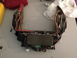
So the first thing I did was strip everything off the models and remove all the brushes and motors associated with its true purpose: vacuuming. I put all the unnecessary pieces to the side. Then I removed all the electronics, sensors, and motors and put them to the side. I then set about washing and scrubbing the dirt off the chassis. Here are some before shots of the robots.


These images do not really convey the level of dirt involved. Next I used some pressurized air to clean dirt off the electronics and wheels. Finally put the wheels and basic electronics back together. I left off most of the sensors for now, figuring I would get the basics to work first. Besides I am mostly interested in just using the wheels for mobility, the battery for power, and the encoders for odometry. I will then mount a camera, the Arduino and some form of processing board (maybe a PC104) on it for image processing. Here is the reassembled shell all nice and clean.


Next, I will look into hooking a cable up to the s-video type connection near the power connector and see if I can make it do some basic functions.

Sunday, May 6, 2012

Using Odometry for Dead Reckoning with the Arduino and a 4WD DFRobot (Part I)


Now that the robot is moving better (the extra L293D chips and capacitors have improved things), it is time to start looking into estimating the robot state over time. I thought I would start simple using just odometry and the ultrasonic sensors. This will also enable me to validate some of the odometry measurements. I have reasonable expectations on the quality of the results. Everything I have read leads me to believe this will not be very accurate. First, here is the parts list (it is getting quite long):
  1. Arduino: Arduino Uno R3
  2. Robot platform: http://www.dfrobot.com/ 
  3. Motor shield: https://www.adafruit.com/products/81
  4. XBee wireless kit: http://www.amazon.com/CanaKit-Xbee-Wireless-Kit/dp/B004G1EBOU/ref=sr_1_9?ie=UTF8&qid=1331990327&sr=8-9
  5. HY-SRF05: https://www.virtuabotix.com/feed/?p=209
  6. Wheel encoders: http://www.dfrobot.com/index.php?route=product/product&filter_tag=encoder&product_id=98
Next I need a state model. Again, starting simple, the robot pose can be represented as X, Y, θ. This position / orientation model is discussed in several papers. A couple of key links that fully describe this approach are:
  1. http://rossum.sourceforge.net/papers/DiffSteer/DiffSteer.html
  2. http://www-personal.umich.edu/~johannb/Papers/pos96rep.pdf
  3. http://www.ecse.monash.edu.au/centres/irrc/LKPubs/ICRA97a.PDF
Obviously, the DFRobot has four wheels and will not be perfectly modeled using this differential steering model. More likely, it will be better modeled using a tracked robot (or crawler). However, I have to start somewhere and this is the easiest. Starting this very simple model differential steering model, we have two sensors (the encoders) that are producing measurements about how far each wheel has rotated. Using the nomenclature specified by Lucas (see rossum reference), the encoders provide Sl and Sr or the distance each wheel has traveled since the last measurement.

Currently, the github code returned the counts provided by the optical encoder. To convert those counts to meters, we need to make a few adjustments. Based on the wheel encoder data sheet, there are 20 PPR (pulse per revolution) made. This means 20 returns is a full wheel revolution. The wheel is about 0.0635m in diameter (2.5 in). Converting this to the circumference, the Sl / Sr measurements are:

  inline float convert(int count) 
  { 
     static const float pi = 20.0f;
     static const float ppr = 3.1416f
     static const float diameter = 0.0635f; 
     static const float circumference = pi * diameter; 
     return circumference * count / ppr;
  }


I inserted this code into the wheel encoder class so now the values returned are the distance in meters. Next is the representation of the state. I added a new class to the trunk at device/platform/dfrobot/state. This class will represent the state of the robot given encoder updates at regular intervals. Initially, this will be just a simple linear prediction model, but will evolve as more sensors are added. First, the state can be represented explicitly using the equations given in here:

s = (Sr + Sl) / 2
θt = (Sr - Sl) / b + θt-1
xt = s cos(θt) + xt-1
y= s sin(θt) + yt-1


where b is the baseline between the wheels. This means the current state at time t is based on an incremental update to the previous state based on the  current measurements. Obviously this integration is going to be very noisy and subject to drift. But nonetheless, it is a starting point. I started with a simple sketch that drove the robot forward, paused, then backward. I repeated this several times with the robot heading towards a wall and away. Using this with the ultrasonic range sensor, I should see the range distance decrease while the position increases and visa versa. Here is a short movie of the robot moving:


Next, I made a plot of the distance sensor output versus the robot x position:

which clearly shows the relationship I was expecting. Next, here is a plot showing the x/y position of the robot in the world:
Again, the code to make this plot is at the github site:
https://github.com/mark-r-stevens/Ardadv/tree/master/device/platform/dfrobot/state/test01
next up, I will look at more complicated maneuvers with different wheel speeds and see how well the model works. I will also start validating the distances traveled by measuring the actual robot location.

Thursday, May 3, 2012

Using ROS (Robot Operating System) Fuerte with the Arduino

I decided to upgrade to the new ROS installation called Fuerte. The installation instructions are given on the wiki: http://ros.org/wiki/fuerte/Installation/OSX/Homebrew/Source. This was a little bit of a challenge as I have been using macports. So I decided to try out homebrew. I decided to do this as that is what is recommended for OpenCV so I figured I would have to do this sooner or later.

I moved my macports installation temporarily to my home directory (sudo mv /opt/local ~/macports). Then I followed the instructions exactly as shown on the installation page (linked above). I only really ran into one problem with the installation. That was with the step:


brew install ros/fuerte/swig-wx


for some reason, my installation did not like the hyphen in the swig formula. I got this error:
swig-wx/usr/local/Library/Taps/ros-fuerte/swig-wx.rb:4: syntax error
To fix the problem, I first had to rename the directory:
cd /usr/local/Library/Taps/ros-fuerte/
mv swig-wx.rb swigwx.rb 
The I edited the file:
vi /usr/local/Library/Taps/ros-fuerte/swigwx.rb
and removed the hyphen from the Swig-wx class.  Then I repeated the homebrew install (this time without the hyphen):
brew install ros/fuerte/swigwx
The formula was still not right, so I had to do a manual install:
cd /Library/Caches/Homebrew/swigwx--git
./configure
make
make install
I then resumed the ros installation process. Everything else worked fine. Here is my /usr/local/Library/Taps/ros-fuerte/swig-wx.rb  file:

require 'formula' class SwigWx < Formula 
   homepage 'http://www.swig.org' 
   url 'git://github.com/wg-debs/swig-wx.git', {:using => :git, :tag => 'upstream/1.3.29'} 
   
   def install 
     ENV.universal_binary 
     system "./configure" 
     system "make" 
     system "make install" 
   end 
 end

Wednesday, April 25, 2012

AdaFruit Motor Shield and the DF Robot 4WD

The last test was a good first test in that the robot moved on command and all the sensors appeared to return output (three ultrasonic sensors and the two encoders). Now it is time to deal with the power issues on the motors. First, the motors do not seem to move at all at speeds less than 200 (as specified to the AFMotor library). This implies there is not enough current going to the motors. In searching the data sheets for the motor (see http://www.dfrobot.com/index.php?route=product/product&path=47&product_id=100) they are listed at 6V and 1.2A. In looking at the data sheet for the AdaFruit motor shield (see http://www.adafruit.com/products/81), the shield 0.6A per bridge (and there are two) and up to 25V. Seems that there is just not enough current per bridge. According to their faq (see http://www.ladyada.net/make/mshield/faq.html), they recommend two things. First attach capacitors to the motor to provide better power regulation, and the second is double up on the L293D chips to improve power output. Seems like both are needed as I am seeing both problems.


First, I decided to measure the power draw before doing anything. This means pulling everything apart and attaching the multimeter to one of the motors. I created the simplest sketch I could create. This just runs each of the forward motors at a speed of 100, then turns them off. This repeats indefinitely until powered off.
  1. #include <AFMotor.h>

  2. AF_DCMotor motor1(1);
  3. AF_DCMotor motor2(2);
  4. AF_DCMotor motor3(3);
  5. AF_DCMotor motor4(4);

  6. void setup() 
  7. {
  8.   motor1.setSpeed(100);  
  9.   motor2.setSpeed(100);  
  10.   motor3.setSpeed(100);  
  11.   motor4.setSpeed(100);
  12. }
  13. void loop() 
  14.   motor1.run(FORWARD);  
  15.   motor2.run(FORWARD);  
  16.   motor3.run(FORWARD);  
  17.   motor4.run(FORWARD); 
  18.   ::delay(5000); 
  19.   motor1.run(RELEASE); 
  20.   motor2.run(RELEASE);  
  21.   motor3.run(RELEASE);  
  22.   motor4.run(RELEASE);  
  23.   ::delay(5000);
  24. }
Here is a picture of the connection of the multimeter right to the power terminals on one of the motors.


 Next, I soldered some capacitors over the motor connectors. This will help regulate the voltage. I used .1uf ceramic capacitors as recommended by the ada fruit motor shield faq. Here is a picture of the capacitor and the solder job to mount them on the motors. This took a little bit of work to get the solder iron close to the leads without having to take the motors out. I would recommend soldering these on before you put the motors in the chassis. I then repeated the test with the volt meter and observed the measurements were much more stable (about 1.7 consistently).


The final step was to double up the L293D chips. First I soldered one chip on top (make sure the U shapes are aligned). and then mounted them. I repeated the simple sketch again and now the wheels start moving at about speeds of 60. Definitely better than before.


Next up, put everything back together and try driving around again. I will also output the encoder and wheel information in ros messages so that it will be easier to record data.

Saturday, April 14, 2012

Using ROS (Robot Operating System) Electric with the Arduino


While I wait for parts (extra L293D chips) to improve the current usage on my dfrobot, I thought I would play around with using ROS and the Arduino. ROS provides several tools, mostly on the host side, that will improve visualization of data coming off the robot. Also has some other handy features for messaging so I will not have to do as much serial string parsing. The main web site for ROS is http://www.ros.org/wiki/. I started out following the installation instructions located at http://www.ros.org/wiki/ROS/Installation. Since I already use macports, the specific instructions I followed are at http://www.ros.org/wiki/electric/Installation/OSX/Macports.

The instructions were straight forward so I will not repeat them here. As usual, whenever I update macports it is a several hour process where lots of out of date things are downloaded and installed.  I did have one slight problem in one of the steps. The command:

rosinstall ~/ros "http://packages.ros.org/cgi-bin/gen_rosinstall.py?rosdistro=electric&variant=desktop-full&overlay=no"
Returned an error about tar returning an incorrect version:
ERROR in config: Unable to create vcs client of type tar for ~/ros: "tar --version returned invalid string: 'bsdtar 2.8.3 - libarchive 2.8.3'"
I was able to fix this by changing the link as to which tar was used:
  1. $ sudo rm /usr/bin/tar
  2. $ sudo ln -fsv /usr/bin/gnutar /usr/bin/tar
Then, the rosinstall command hung. For some reason, I had a version of rosinstall in /usr/local/bin. I am not sure how it got there. I used the full path to rosinstall to make sure that it was pulling in the right version. Something to be aware of in the future:

    1. /opt/local/bin/rosinstall ~/ros "http://packages.ros.org/cgi-bin/gen_rosinstall.py?rosdistro=electric&variant=desktop-full&overlay=no"
Several macports project dependencies were needed. A few times I needed to kill the python install and then run the sudo maports install manually. Apparently ros wants gnu tar and macports wants bsdtar. There must be an easier way around what I did. Then restarted the install script. When that was finished, I proceeded to test the installation. First thing I needed to do was add my machine name to /etc/hosts (which now has the line below for my machine name, yoshi, which is now an alias for localhost):
  1. 127.0.0.1 localhost yoshi
I was then able to run a few simple commands to start an ROS session:
  1. roscore > /dev/null &
  2. rosmake turtlesim
  3. rosrun turtlesim turtlesim_node &
  4. rosrun turtlesim turtle_teleop_key 
which let me use the mouse keys to drive a turtle around in a window (see below).


Once ROS was installed, I looked into how to get ROS and the Arduino to communicate. Turns out there is a package called rosserial that is used to send messages back and forth, see the link http://www.ros.org/wiki/rosserial. First I installed the packages:


  1. cd ~/ros
  2. source setup.bash
  3. hg clone https://kforge.ros.org/rosserial/hg rosserial
  4. export ROS_PACKAGE_PATH=~/ros/rosserial:$ROS_PACKAGE_PATH
Note this last step was not provided anywhere and took me a while to figure out. If you do not add the package to the ROS_PACKAGE_PATH then none of the ros commands will work. Next I needed to build rosserial. I do not usually compile aurduino code using macports (I use the Arduino.app) so I needed to install that first:
  1. cd ~/ros
  2. sudo port install avr-gcc 
  3. rosmake rosserial_arduino
  4. rospack profile
  5. roscd rosserial_arduino/libraries
  6. cp -R ros_lib /Applications/Arduino.app/Contents/Resources/Java/libraries
Next, I used one of the rosserial examples that reads out analog pins (see http://ros.org/wiki/rosserial_arduino/Tutorials/Arduino%20Oscilloscope):

  1. #include <ros.h>
  2. #include <rosserial_arduino/Adc.h>

  3. rosserial_arduino::Adc adc_msg;
  4. ros::NodeHandle nh;
  5. ros::Publisher p("adc", &adc_msg);

  6. void setup()
  7.   pinMode(13, OUTPUT);
  8.   nh.initNode();
  9.   nh.advertise(p);
  10. }
  11. void loop()
  12. {
  13.   adc_msg.adc0 = analogRead(0);
  14.   adc_msg.adc1 = analogRead(1);
  15.   adc_msg.adc2 = analogRead(2);
  16.   adc_msg.adc3 = analogRead(3);
  17.   adc_msg.adc4 = analogRead(4);
  18.   adc_msg.adc5 = analogRead(5);
  19.   p.publish(&adc_msg);
  20.   nh.spinOnce();
  21. }
Then I fired up a few ros commands (note the second command was needed to make sure the python serial interface was installed):
  1. roscore &
  2. sudo port install py26-serial
  3. sudo port install py26-matplotlib 
  4. sudo port install py26-wxpython
  5. rosmake rxtools --rosdep-install
  6. rosrun rosserial_python serial_node.py /dev/cu.usbmodem621 &
  7. rostopic list
  8. rxplot adc/adc0
Note that step #4 was simply to make sure the topics was being generated properly. These steps produced the plot shown below.


Turned out setting up ros to work with the Arduino was quite a bit of work. I think it will be worth it down the road though as it opens up a wide range of tools that can be used.

Good Luck!

Friday, April 6, 2012

Driving the DFROBOT around


Now that I have software for the wheel encoders, the range sensor, the motor shield and a simple GUI to control things, it is time to start putting all the pieces together. After trying several things to mount the range sensor on the robot (rubber bands, electrical tape, plexiglass mount), I decided to order a small sensor housing from lynx motion (http://www.lynxmotion.com/p-397-multi-purpose-sensor-housing.aspx). I just had a hard time finding the small screws to properly mount the ultrasonic sensor. The lynx motion mount worked well, although I decided to drill a few holes in the platform to mount three of them at the angles I wanted. Here are a few images of the mounts. This picture shows the range sensor (top left), the mount (top right) and the range sensor on the mount (bottom).


Next, I mounted three of them on the dfrobot. Hopefully, this will give some useful data for robot localization (besides just obstacle avoidance). Here is a picture of the three sensors mounted on the front of the robot.


Next I decided it was time for some re-wiring. I had been just sticking wires together without much organization to get things hooked up. This made it impossible to easily take things apart as the wires were soldered (on the motor) or screwed down (on the motor shield). I ended up soldering some stackable headers on one end of the connection, and header pins on the other to make a cheap connection. This was a little trick recommended in the book http://www.amazon.com/Robot-Builders-Bonanza-4th-Edition/dp/0071750363/ref=sr_1_1?ie=UTF8&qid=1333630892&sr=8-1. Here is a picture of the soldering.


I made sure to label which motor went with which pin. Here is a picture after all the taping and soldering and labeling.


Next up was getting a battery mounted so the Arduino could run without the USB cable running out the back. I searched the web, but did not find much discussion about the best way to do this. I think I have just not hit the right keywords yet. Any suggestions on batteries? 

Seems that LiPo are the way to go. I figured that I would try something simple first and see how long the batteries last before moving onto a better battery solution. I decided to take a trip over to radio shack and found a 9v connector and a barrel jack. I soldered them together and mounted the 9 volt on the robot chassis.


The final change was to mount the Arduino to the chassis. Being paranoid, I was worried that the having the Arduino header pins sitting on the metal chassis would cause cross talk amongst header pin voltages. At radio shack I found some cheap PC mounts. I needed to get out the dremel though as the pins interfered with the mounts (see below). Cutting little slits in the mounts let it sit properly and now everything is rigidly mounted and I am not to worried about shorts.


Then it was putting everything together. Here are a few pictures of the result.


So finally, here is the parts list.
  1. MegaShield: http://store.nkcelectronics.com/megashield-kit.html
  2. Arduino Mega: http://arduino.cc/en/Main/ArduinoBoardMega
  3. Jumper wires
  4. ROB0025: http://www.dfrobot.com/ 
  5. AdaFruit motor drive shield: https://www.adafruit.com/products/81
  6. Wheel encoders: http://www.dfrobot.com/index.php?route=product/product&filter_tag=encoder&product_id=98
  7. Range sensors: http://www.amazon.com/Virtuabotix-Ultrasonic-Rangefinder-Obstacle-Detection/dp/B0066X9V5K
  8. Xbee: http://www.amazon.com/Xbee-Wireless-Kit-Chip-Antenna/dp/B004WLHE1G/ref=sr_1_3?s=electronics&ie=UTF8&qid=1333322544&sr=1-3
At this point little in the code needed to be code to drive the robot using the gui. Basically, just adding a new unit test that had the range sensors and printed all the measurements. Again, the code for this is located on github at
https://github.com/mark-r-stevens/Ardadv/tree/master/device/platform/dfrobot/manual/test04
I added a few command line parameters to the dfrobot UI so that I can specify the device and port to connect. The first drive was moderately successful (see movie below). Seems that not all the motors are moving all the time and the wheels seem to slip a lot. To get the robot to move I need to use the maximum speed. I will need to tackle this next. Possibilities that I have found are adding more battery power, doubling up the L293D chips on the motor shield (get more amps), and using capacitors on the motors (better power regulation). All of these things are possibilities I will start looking at next.


One note about the movie, seems that there is some latency in the video acquisition. I will also look into this for better grabbing of frames that sync up with the robot motion. Lots left to do and experiment!