Friday, March 30, 2012

Using the SEN0038 wheel encoders, the Arduino, and interrupts

Now that I got the ultrasonic sensor to work and the MEGA board on the robot, it is time to tackle the wheel encoders. The ROB0025 comes with the SEN0038 wheel encoder. The first step is to get the encoders mounted on the robot. This was a little challenging given how small the screws were. Plus getting them spaced right so the spinning wheel was centered between the diode took a little trial-and-error with the right set of washers.

First up, the parts list. The parts from previous projects were needed, plus the new encoders

  1. MegaShield: http://store.nkcelectronics.com/megashield-kit.html
  2. Arduino Mega: http://arduino.cc/en/Main/ArduinoBoardMega
  3. Jumper wires
  4. ROB0025: http://www.dfrobot.com/ 
  5. AdaFruit motor drive shield: https://www.adafruit.com/products/81
  6. Wheel encoders: http://www.dfrobot.com/index.php?route=product/product&filter_tag=encoder&product_id=98
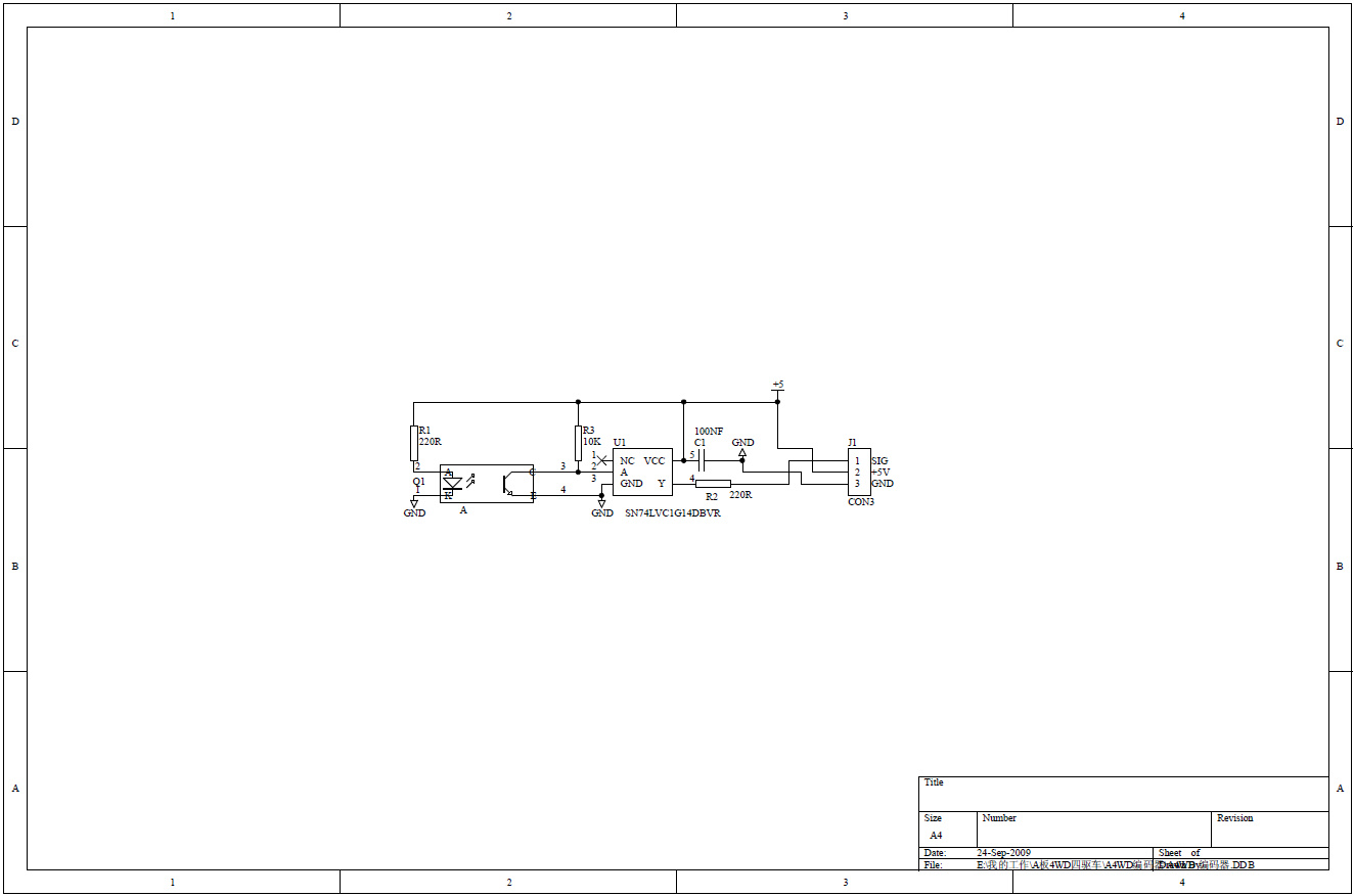
After I wired everything up, I started looking around for some documentation on how to use them. First, here is a picture of the encoders connected.


Then some googling to learn more about the model and product. This turned up several threads about how these encoders do not work. Luckily I traced down a thread which had answers and code about how to make them work (item #3 below).
  1. http://www.dfrobot.com/wiki/images/b/b9/FIT0029_Encoder_Schematics.png
  2. http://dfrobot.com/wiki/index.php?title=Wheel_Encoders_for_DFRobot_3PA_and_4WD_Rovers_(SKU:SEN0038)
  3. http://www.dfrobot.com/forum/index.php?topic=354.0
  4. http://www.dfrobot.com/index.php?route=product/product&product_id=98
To get the encoders to work properly, interrupts need to be used. I spent some time reading up on the best way to do this. Interrupts are used to ensure that all transitions of the wheel are caught. If we were to use polling we would probably miss half the transitions. Reading up on encoders though, they will probably not be all that accurate anyways. Here are a few of the noteworthy links:

  1. http://arduinomega.blogspot.com/2011/05/external-interrupts-buttons-for.html
  2. http://www.engblaze.com/we-interrupt-this-program-to-bring-you-a-tutorial-on-arduino-interrupts/
  3. http://www.codeproject.com/Articles/61023/Arduino-Platform-Interrupts-Introduction
  4. http://www.me.ucsb.edu/~me170c/Code/How_to_Enable_Interrupts_on_ANY_pin.pdf
  5. http://arduino.cc/en/Hacking/PinMapping2560
Getting the interrupt to work properly turned out to be much more challenging than I expected. Many hours were spent trying to figure out what exactly was wrong. I originally hooked up the encoders to use interrupts 2 & 3 (pins 21 and 20). No matter what I tried, I would not get back reasonable results. Most of the time I would get a reasonable count (robot setting with wheels off the table spinning for a second). Usually one wheel would work well, but the other would return nonsensical values in the 1000s. 

More googling turned up this thread, and a pointer to the pololu encoders and library.
Using these posts, I gave up using the Arduino interrupt abstraction and used the AVR library directly. I put the encoders on pins 50 and 51. This worked much better. I am not sure exactly why the Arduino interrupt library did not work with the Mega and the encoders. I checked with the multimeter and the encoders were not fluctuating in voltage when the wheel was not spinning. I did notice that the AdaFruit motor shield was causing subtle power fluctuations that could explain the interrupts misfiring. I did an experiment where I disconnected the motor shield, put the encoders on pins 20 and 21, and spun the wheels by hand. This worked perfectly. So the only thing I can conclude is that it is some combination of trying to use pins 20 and 21 with the configuration I had.

At any rate, hooking the encoders up to pins 50 and 51, and then coding directly to the AVR library for the interrupts seems to have solved my problems. Again the code is located at:
https://github.com/mark-r-stevens/Ardadv/tree/master/device/sensors/encoders
There is an encoders class that abstracts the messy interrupt code (with the global variables) and a simple unit test that spins the left wheel, stops it, then the right wheel and stops it. Wheel encoders counts are made when only one wheel is spinning. This enables me to check that the right encoder is being used when the right wheel is spinning. Here is a plot showing the two wheels.


Next, here is a histogram of the two. Note that in this case, I had the right wheel spin at a speed of 200 and the left wheel spin at a speed of 150. This can be seen from the plot that more values were recorded when the motor was spinning faster (good sanity check).


I will need to convert these to meters based on wheel diameter. However, it was a lot of work to figure out the interrupt problem, so that will need to wait until next time.

Saturday, March 24, 2012

Using the HY-SRF05 Ultrasonic Module with the Arduino

Next on the list of sensors to explore is the ultrasonic range sensor. I am hoping to use this for two things. First, a simple range detector for obstacle avoidance (if something is ahead of you stop and do something else). Second, use the information to improve localization and map building. The latter usage may be a little problematic as it depends on the quality and timeliness of the measurements.

I started to look around at (i.e., google) the various options. To keep things simple, decided on the HY-SRF05 mostly due to the cost and availability on Amazon Prime (that keeps shipping costs down as well). and availability of code out there to make measurements. The parts list for this experiment is very simple.

  1. HY-SRF05: https://www.virtuabotix.com/feed/?p=209
  2. Arduino UNO: http://www.sparkfun.com/products/11021
  3. Some wires:  http://www.sparkfun.com/products/9385
  4. Breadboard: http://www.sparkfun.com/products/9567
As I was looking, I found lots of code and examples about how to wire up the device.

Here is an image of the wiring


Then I setup the sensor and pointed it at a wall. I measured the distance to the wall as 0.381 meters. I collected about 1 minute of returns from the sensor and calculated the mean (0.3888) and standard deviation (3.3548e-04). So things seem pretty close. 


Here is a histogram of the values. 


This was by far the easiest of the sensors to find information about, connect, and get out sensible readings. The hardest part seems to be how to come up with a good way to mount the sensor. As usual, all the code is located on github at:
https://github.com/mark-r-stevens/Ardadv/tree/master/device/sensors/ultrasonic

Upgrading from the UNO3 to the Arduino Mega

I decided that it was time to upgrade from the UNO to the MEGA. I started mapping out how many pins I would need for the accelerometer, the magnetometer, the gyroscope, the wheel encoders, the xbee, the motor drive shield, and the range sensors. The pin count added up to much more than was available on the UNO. The MEGA is about twice the size (physically) and has a lot more potential. I also purchased a prototype shield to help stack some of these devices together. Here are the parts I am using:

  1. http://store.nkcelectronics.com/megashield-kit.html
  2. http://arduino.cc/en/Main/ArduinoBoardMega

First, here is a picture of the two boards side by side.


The shield took some assembly. First here is a look at all the parts (below). Then I soldered all the headers on; this took some effort as there was a lot of soldering to do.


After that, it was onto soldering on the resistor, capacitor and LED. Make sure the LED is hooked up with the long wire connected to the positive terminal. Then the reset and a few of the header pins.


Finally, I stacked the shield, the xbee card and then the motor shield onto a stack.


Finally connected it all to the dfrobot platform. Now I have enough pins on the front to start to look at the encoders and range sensor.


Next, I reworked the CMakeLists.txt files a little bit. I put a top level define for the board and the port:

## Generate code for the specified board
#
set(PROJECT_BOARD uno)

## Set the device 
#
set(PROJECT_DEVICE /dev/cu.usbmodem621)

And then had the lower level build files use those variables. That way I easily change the board to build against at the top level of the tree.

As usual, the code can be found at: https://github.com/mark-r-stevens/Ardadv


Using the DF Robot 4WD (SKU ROB0025) with the Arduino (Part II): Qt user interface.

In the last post, I put together the robot base, wired the motors, and wrote a simple test program to make all the wheels move. The next step is to make a simple user interface to control the robot to get it to drive around. The point really is to enable manual control to drive the sensors around and record measurements. Then given the measurements, develop a better controller to improve localization estimates of the robot over time. After that is done, I will add in other sensors that add information about the scene (i.e., video) that will enable rudimentary SLAM capability.

In a previous post, I had written a UI in Qt (http://qt-project.org/). Qt is a UI toolkit that comes with a lot of examples, is open source, and fairly straight forward (as widget toolkits go) to use. I realize many people might think of developing user interfaces as a daunting task. There are several basic tutorials out there that can be uncovered with a little googling (http://www.instructables.com/id/Control-your-arduino-from-your-PC-with-the-Qt-Gui/).

I have taken a pretty simple approach. Use OpenCV (http://opencv.willowgarage.com/wiki/) to grab camera images from a web cam and display them in a Qt OpenGL widget. Then have a second widget that enables robot motion control. I thought for awhile about the easiest widgets to use for control. Sliders and push buttons came quickly to mind. After some thought, I decided to use mouse movement in a 2D cartesian coordinate system. This enables easy mapping of left and right motor speed to a single point in the 2D grid. Moving the mouse around changes the ratio and spin speed of the wheels on both side of the robot. I figure this will let me figure out the robot dynamics and eventually build a fairly good controller.

Here is a screen shot. On the left is the webcam image, on the right is the 2D wheel speed grid. To send the commands, hold down the control key and move the mouse in the 2D grid. Releasing the key will stop the motors. This allows a virtual "kill switch" if the robot gets too out of control.

I also downloaded some code to interact with the Arduino over a serial connection. Most of the libraries I found were overly complicated for what I needed. Eventually I came across the four functions I was looking for at the site http://www.ontrak.net/linux.htm. I wrapped this code in a simple threaded Qt class that has a signal to connect to receive data from the Arduino. The data can be written through a slot (with a mutex around to prevent collision).

On the device side, I downloaded some code to parse incoming messages from the device. There is a heavyweight library called Shine (see https://sites.google.com/site/shinearduino/home/why-use-shine). This seems like overkill for the first implementation. There is also a library called SimpleMessageSystem (see http://www.arduino.cc/playground/Code/SimpleMessageSystem). Like the name says, this seems like exactly what I was looking for .... simple. After some more digging, a newer version of the library exists called CmdMessenger (see http://arduino.cc/playground/Code/CmdMessenger). Has a similar type interface in that you send a command id (in this case I am using 4 as the motor control command) followed by comma separated values, terminating in a semi colon.

I set things up so command 4 controls the motors, and the next two numbers are the speed of the left and right motors respectively. This means sending "4,100,100;" will cause both wheels to move forward and "4,-100,-100" will cause them to move backwards. In playing around with the speeds it seems that nothing much below 100 causes the wheel to turn. Looking on the web, a few places have suggested using an extra capacitor to smooth out the motor power. I will look into that once everything is up and moving.

So the code to receive the commands and send the speeds to the motors is located in:

https://github.com/mark-r-stevens/Ardadv/tree/master/device/platform/dfrobot/manual/test03
Once that is uploaded, then the UI program can be started. The code for that is located at:

https://github.com/mark-r-stevens/Ardadv/tree/master/host/dfrobot
The serial port to connect to is hard-wired in the code. That is something I will need to fix. When this runs, holding down control and moving the mouse around causes the wheels to move. Here is a movie of the wheels moving:


Next up is hooking in the xbee and the wheel encoders. I also need to wire up a battery connection so that it can drive un-tethered. Luckily my Mega board arrived today so I will switch over to using that to gain access to some much needed ports.

Monday, March 19, 2012

Using the DF Robot 4WD (SKU ROB0025) with the Arduino (Part I)

The robot kit arrived today and I started to assemble things. There were no instructions in the package so it took a little trial and error to figure out which nuts and bolts held things together. The main confusing point was there were far more pieces than I needed to put the thing together. I think that the extra hardware is present so things can be added to the chassis later (as needed). The project took about 2 hours to get the chassis fully assembled. Part of the trouble was the screws to mount the motors were very tiny and hard to place onto the chassis to tighten. It took about 10 minutes to get the wheels with the encoders into the proper setup.

The parts list needed for the (start) of this experiment are:
  1. Arduino Uno R3
  2. Jumper wires
  3. http://www.dfrobot.com/ 
  4. https://www.adafruit.com/products/81
After starting to put things together, I wanted to make sure I was doing everything correctly. There are several pages I found that were helpful in putting things together:


One of the tricky part was how to setup the power switch. When I first wired things up, I did not connect the switch. I simply wired the battery pack to the motor shield and the motors started up right away. This caused problems when I was testing out making the motors spin as there was no easy way to turn things off. Since there were no instructions, I had to wing it on connecting the switch. Not too complicated as there are three connections on the switch. A little testing with the multimeter showed which connections should be used for off and on. Here is a picture of the switch connection. I think I will also investigate getting a rechargeable batter at some point as the batteries are somewhat hard to get to in this configuration.


Next it was onto the code. I wanted to do something simple at first to just test that the four wheels were all wired properly and moving in the right direction. Again, the code is posted at the github site:


There is a class called Manual that will eventually be used to remote control the robot to move around the room. My current plan is to finish up getting the sensors setup to record measurements. Then manually drive the robot in circles to collect sensor measurement data and make some plots of the various sensor readings (encoders, accelerometer, magnetometer, gyroscope). I only have a few more sensors to hook up and then write code to dump all the data to a serial port. I also need to write the manual controller and play around with steering. However, I have realized that I do not have enough pins on the Arduino to hook everything up. I ordered a mega board so that I can be sure to collect enough measurements. Next up, will be writing code for the ultrasonic range sensor. That should allow some crude obstacle avoidance and maybe some initial estimates for SLAM.

Here is a quick movie of the wheels spinning with the simple test program.


Saturday, March 17, 2012

Using the XBee with the Arduino on Mac OS X

While I have only been tinkering around with the Arduino now for a few weeks, I have quickly realized that I need to be able to interact with the board over a wireless connection. A tethered robot is not all that exciting (unless you are talking about Big Dog or the new Cheetah Boston Dynamics has developed). I spent some time trying to figure out the best wireless connection to use. There seems like there are many options: bluetooth, XBee, ZigBee, etc. After reading the Sparkfun XBee Buying Guide it seems like the XBee is the best (easiest?) way to go. So I ordered a XBee Wireless Kit as that seemed to have all the pieces I would need. Now the hard part seems to be how to configure the card on the mac (I suppose I could fire up a windows VM, but that seems just wrong). First off the parts list used for this experiment:

  1. XBee wireless kit: http://www.amazon.com/CanaKit-Xbee-Wireless-Kit/dp/B004G1EBOU/ref=sr_1_9?ie=UTF8&qid=1331990327&sr=8-9
  2. Arduino UNO 3: http://www.sparkfun.com/products/11021
The first step is to put the kit together. Here are some pictures before and after assembly:


Next I started looking around for some tutorials on how to connect and send / receive data. There were several sites that were useful:
  1. http://www.faludi.com/itp_coursework/meshnetworking/XBee/XBee_program_Arduino_wireless.html
  2. http://ftp1.digi.com/support/documentation/90000982_A.pdf
  3. http://bildr.org/2011/04/arduino-xbee-wireless/
The first step was to install the FTDI drivers. I downloaded them from this site http://www.ftdichip.com/Drivers/VCP.htm. I installed them allowing the host computer to talk to the connected explorer USB board. Then I needed a way to configure the XBee for peer-to-peer communication (as I only have two chips right now). I was using screen on the mac to see output from my previous tests. That is a little cumbersome. I decided to try zterm (downloaded from http://www.macupdate.com/app/mac/6888/zterm-x) in the hopes that would be a little better.

First, I plugged the XBee on the USB explorer card into my machine. Then I started up zterm. Then under Settings->Modem Preferences, I selected the usb serial device name. To find this I just selected the one that I did not recognize. I also checked in /dev for the date and time of the device to make sure it coincided with when I plugged it in. Then under settings->connection make sure the data rate is set to 9600. The two dialog boxes are shown below.
The wake up sequence is "+++" with no enter. When I typed that I got back "OK", I then typed "ATID" and received back 3332. All looks good and is what was expected based on arduino-xbee-wireless. Then using the guidelines at XBee_program_Arduino_wireless, I issued this command for the first xbee card:
ATID4321
which changes the network id to 4321. You should pick your favorite four digit pin.
ATID4321,DH0,DL1,MY0,BD4,WR,CN
which increases the baud rate to 19,200 and sets the address to 0. I repeated the process for the second card. This time, the command is:

ATID4321,DH0,DL0,MY1,BD4,WR,CN
which increases the baud rate and assigns the second card the address to 1. I then changed the zterm connection data rate to 19,200 and was able to re-issue the "+++" command and the "ATID" to see the new id. The shield I was using has a toggle on it to switch back and forth between UART and DLINE. This lets the code be downloaded using the USB to Arduino and then the serial line to send back and forth data. I created a very simple sketch:

  1. void setup()  
  2. {
  3.   delay(1000);
  4.   Serial.begin(19200);
  5.   Serial.flush();
  6. }
  7. void loop()  
  8. {
  9.   Serial.print("\rHello>");
  10.   while (Serial.available()) 
  11.   { 
  12.     char inByte = Serial.read(); 
  13.     Serial.println(inByte);
  14.   }
  15. }
I uploaded this, unplugged the Arduino, and then fired up zterm. When I type something in zterm it is echoed back with a hello prompt in front. So this allowed wireless data to be exchanged once the sketch was uploaded to the Arduino.

Friday, March 16, 2012

Using the AdaFruit drive motor shield with the Arduino: wheels on the bus go....

Lots of parts arrived this week. The first part was the AdaFruit drive motor shield. I picked this shield as it has the ability to drive four DC motors. Most other shields I looked at only supported two motors. The second part was the 4WD dfrobot kit. I choose this kit as it has plenty of room for sensors on the top, a power supply and wheel encoders. I was specifically interested in the wheel encoders so I can grab information about how far the robot has moved (or think it has moved). That information can feed into the filter estimate of robot localization over time. The parts list for this experiment was:

  1. Arduino Uno R3
  2. Jumper wires
  3. http://www.dfrobot.com/ (although I am just using the motors for this one)
  4. https://www.adafruit.com/products/81
The first step was to put together the motor drive shield. This was fairly straight forward as AdaFruit put together a comprehensive installation guide. It took about an hour to solder everything together. I then hooked up the shield and was able to run a sample test to have the motor run forward and backward repeatedly. One step I forgot at first was to use the jumper on the power to use the 9 volt external power supply from the Arduino board. This will not be needed when I switch to the battery pack on the robot. As is pointed out several times throughout the AdaFruit guides, make sure that the LED light is on if you want to get the motors to run.

Here are a few pictures of the initial set of parts and the shield once it was all assembled:


The code for making the motor run forward and back is located in my github folder at:

https://github.com/mark-r-stevens/Ardadv/tree/master/device/actuators/motor/test

Next up, I will start on wiring up the other motors and assembling the dfrobot kit. I also decided that I needed to wirelessly control the robot so I ordered an xbee board so I could send it commands remotely. I may work on that next and then switch over to assembly (plus there is the whole issue of figuring out the encoders).