Now that I have software for the wheel encoders, the range sensor, the motor shield and a simple GUI to control things, it is time to start putting all the pieces together. After trying several things to mount the range sensor on the robot (rubber bands, electrical tape, plexiglass mount), I decided to order a small sensor housing from lynx motion (http://www.lynxmotion.com/p-397-multi-purpose-sensor-housing.aspx). I just had a hard time finding the small screws to properly mount the ultrasonic sensor. The lynx motion mount worked well, although I decided to drill a few holes in the platform to mount three of them at the angles I wanted. Here are a few images of the mounts. This picture shows the range sensor (top left), the mount (top right) and the range sensor on the mount (bottom).

Next, I mounted three of them on the dfrobot. Hopefully, this will give some useful data for robot localization (besides just obstacle avoidance). Here is a picture of the three sensors mounted on the front of the robot.

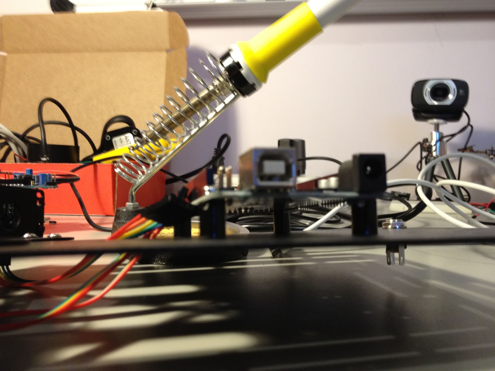
Next I decided it was time for some re-wiring. I had been just sticking wires together without much organization to get things hooked up. This made it impossible to easily take things apart as the wires were soldered (on the motor) or screwed down (on the motor shield). I ended up soldering some stackable headers on one end of the connection, and header pins on the other to make a cheap connection. This was a little trick recommended in the book http://www.amazon.com/Robot-Builders-Bonanza-4th-Edition/dp/0071750363/ref=sr_1_1?ie=UTF8&qid=1333630892&sr=8-1. Here is a picture of the soldering.

I made sure to label which motor went with which pin. Here is a picture after all the taping and soldering and labeling.

Next up was getting a battery mounted so the Arduino could run without the USB cable running out the back. I searched the web, but did not find much discussion about the best way to do this. I think I have just not hit the right keywords yet. Any suggestions on batteries?
Seems that LiPo are the way to go. I figured that I would try something simple first and see how long the batteries last before moving onto a better battery solution. I decided to take a trip over to radio shack and found a 9v connector and a barrel jack. I soldered them together and mounted the 9 volt on the robot chassis.


Then it was putting everything together. Here are a few pictures of the result.


So finally, here is the parts list.
- MegaShield: http://store.nkcelectronics.com/megashield-kit.html
- Arduino Mega: http://arduino.cc/en/Main/ArduinoBoardMega
- Jumper wires
- ROB0025: http://www.dfrobot.com/
- AdaFruit motor drive shield: https://www.adafruit.com/products/81
- Wheel encoders: http://www.dfrobot.com/index.php?route=product/product&filter_tag=encoder&product_id=98
- Range sensors: http://www.amazon.com/Virtuabotix-Ultrasonic-Rangefinder-Obstacle-Detection/dp/B0066X9V5K
- Xbee: http://www.amazon.com/Xbee-Wireless-Kit-Chip-Antenna/dp/B004WLHE1G/ref=sr_1_3?s=electronics&ie=UTF8&qid=1333322544&sr=1-3
At this point little in the code needed to be code to drive the robot using the gui. Basically, just adding a new unit test that had the range sensors and printed all the measurements. Again, the code for this is located on github at
https://github.com/mark-r-stevens/Ardadv/tree/master/device/platform/dfrobot/manual/test04I added a few command line parameters to the dfrobot UI so that I can specify the device and port to connect. The first drive was moderately successful (see movie below). Seems that not all the motors are moving all the time and the wheels seem to slip a lot. To get the robot to move I need to use the maximum speed. I will need to tackle this next. Possibilities that I have found are adding more battery power, doubling up the L293D chips on the motor shield (get more amps), and using capacitors on the motors (better power regulation). All of these things are possibilities I will start looking at next.
One note about the movie, seems that there is some latency in the video acquisition. I will also look into this for better grabbing of frames that sync up with the robot motion. Lots left to do and experiment!
No comments:
Post a Comment