Slave Select pin - the pin on each device that the master can use to enable and disable specific devices. When a device's Slave Select pin is low, it communicates with the master. When it's high, it ignores the master. This allows you to have multiple SPI devices sharing the same MISO, MOSI, and CLK lines.As I understand this, it means I can have both of them share the pins except for the slave pin. All I have to do is tell the one device to ignore the SPI while the other device is being used. A little searching on the web turned up this tutorial http://tronixstuff.wordpress.com/2011/06/15/tutorial-arduino-and-the-spi-bus-part-ii/. First, I need to make sure both measurement devices are all wired up and connected properly. Turns out to do this on my pan/tilt servo required a lot of wires. This has me thinking that at some point when this is all figured out I need a more permanent solution as this will be impossible to keep wired properly. Here is a wiring diagram and a photo of how things are set up.
Next, I repeated what I did before with the gyroscope: turned the servo on, rotated it back and forth and recorded the measurements of the heading from the magnetometer. There is a slight bias subtraction I did to account for the fact that the starting orientation of the magnetometer is 135° off from north. This led to the following plot:
Using a period of 128 for the magnetometer proceed really noisy results. Here is a plot showing using a period of 32.
Still pretty noisy. An averaging filter will be very sensitive to these outliers. As an example here is an IIR filter applied to this using a 0.1 weighting factor:
This dampens the spikes, but is still very noisy. Just for completion, here is a median filter run. This looks better, but requires more computation to compute (and measurement latency).
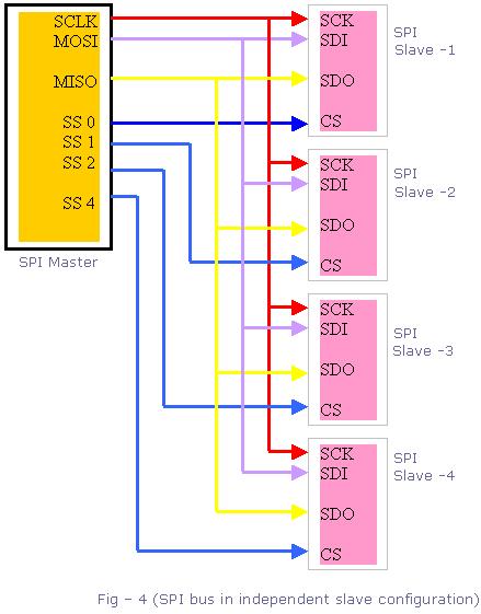
Now back to the gyroscope. To use the SPI interface for both, I needed to rework the code a little. The SPI setup calls are different for both sensors, so I needed to reset the SPI before calls to update the measurements for each sensor. Then I had to set the slave select pin to low for both devices after the update. A good overview of what needs to be done is at http://www.eeherald.com/section/design-guide/esmod12.html:
1. All the clock lines (SCLK) are connected together.
2. All the MISO data lines are connected together.
3. All the MOSI data lines are connected together.
4. But the Chip Select (CS) pin from each peripheral must be connected to a separate Slave Select (SS) pin on the master-microcontroller.
So the useful links I used to figure this out are:
- http://www.arduino.cc/cgi-bin/yabb2/YaBB.pl?num=1227719581
- http://www.arduino.cc/cgi-bin/yabb2/YaBB.pl?num=1284605439/6
- http://www.eeherald.com/section/design-guide/esmod12.html
Using this I am now able to make measurements from both simultaneously. Here is a plot showing the two outputs:
This shows the drift from the gyroscope and the noise from the magnetometer. Next steps will be to combine the two and produce a result that provides a solid heading estimate. I also have to figure out the scaling of the gyroscope during integration. When I account for dt using millis() it does not provide very accurate results.


No comments:
Post a Comment