Today I started on my first Arduino project. As seems to be the fashion, I decided to work with a set of LEDs and turn them on and off with a push button. This seems like a good place to start as I will have to build code, wire something up, and there seems to be minimal chance I could screw things up too badly. I also wanted to play around with serial output. This will be needed for the next adventure where I start logging and visualizing accelerometer outputs. The plotting and what not will be done on the host so the serial data for the measurements will need to be transferred back.
Here are the parts that I used:
- Protoype shield for the Arduino
- Arduino Uno R3
- Jumper wires, colored LED, push button, and several resistors
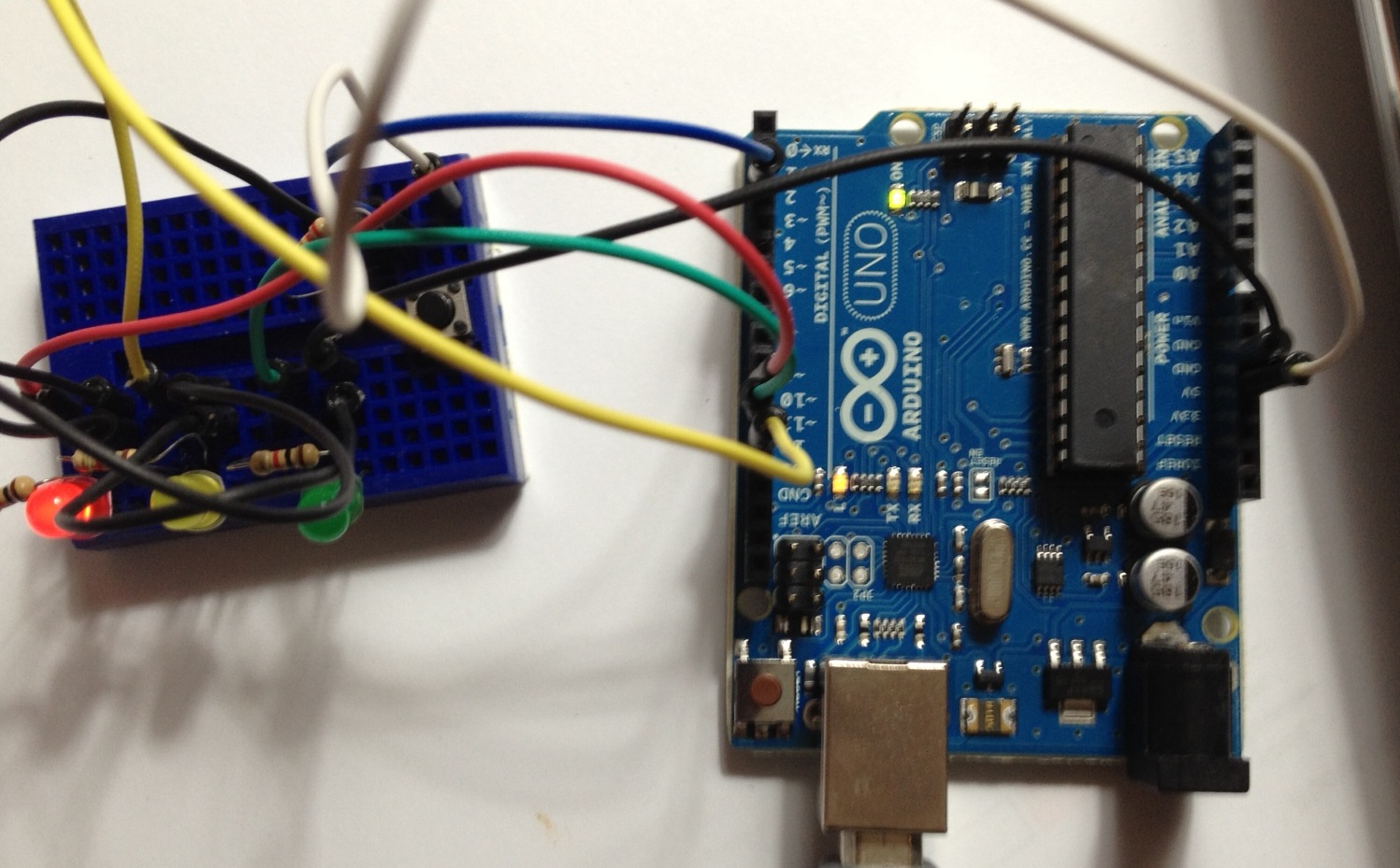
The LEDs were hooked up with resistors on pins 10, 11, 12. The push button was hooked up with a pull down resistor on pin 2 (powered but 5v) and everything was grounded. The wiring setup is shown in the picture below.
I created a github site to store the code for the various experiments. This site is located at this site. For simplicity, you can grab the code by cloning the entire repository using the command:
git clone git@github.com:mark-r-stevens/Ardadv.git
The code for this example is in Test/Test00. Things I learned with this simple example:
- The loop function is called repeatedly so it is possible that the button will be held down and marked as HIGH for many iterations. We only want to change the light on the transition from Released to Pressed. This implies keeping track of the button state and triggering on the event (not the state).
- The Serial line needs to be initialized in setup. Flush also needs to be called so that values get output promptly. The println should flush things, but to be safe I added an explicit flush.
- I need a bigger breadboard. Something with power rails and more space would have greatly simplified the wiring. Also, these get cluttered pretty quick so using colored wires really helps.
- I am getting old. Reading the color coding on these resistors is for the young ;)
- Pictures of the layout is challenging. I will need to get a better breadboard and layout the wires so that you can see things a little better in the images.
The next project will begin work on getting accelerometer readings and trying to estimate platform attitude for initial attempts at dead-reckoning. I have also been surfing to find a small robot platform with wheel encoders.
No comments:
Post a Comment