Showing posts with label Project 1: Small mobile robot. Show all posts

Sunday, March 4, 2012

Using the MMA7361 Accelerometer with the Arduino UNO 3: (Part II)

I left off with a good start on reading and interpreting the accelerometer values. This was not working as well as I had hoped, so I did a little more searching the web and came across a few sources:

  1. http://www.starlino.com/imu_guide.html
  2. http://code.google.com/p/mma7361-library/
  3. http://www.freescale.com/files/sensors/doc/data_sheet/MMA7361L.pdf
These three links provided lots of insightful information. I used that to update my code. I still am not positive everything is working right. I wrote a little visualization routine that will hook up the serial output of the accelerometer and visualize the data coming back plus the orientation. An example is shown below.


This shows that the values are close to one when the dominant axis is pointed down (or -1 if oriented in the other direction). However, the values are not quite zero when sitting still. Clearly a better calibration routine is needed to correct for these slight errors. In these plots, red is the x axis, green is the y access and blue is the z axis. The noise in the output can also been seen in the values along the bottom. However, at least I am convinced that the numbers are in the right ballpark. However, until I have formulated a dynamics model the scaling and calibration is not as high a priority.

I will next switch and repeat the process for a magnetometer. Hopefully this will be fairly easy as most of the work in dealing with accelerometer was setting up infrastructure. I also ordered a small robot kit. When that arrives I will start playing around with wheel encoders and simple navigation using dead reckoning.

Saturday, March 3, 2012

Using the MMA7361 Accelerometer with the Arduino UNO 3 (Part I)

Now that I have coded up a basic LED circuit, I thought I would move on to working with sensors that will measure robot location. Remember the goal of the first experiment is to build a small robot that can use dead reckoning to move through an environment. This is the precursor to developing a SLAM system as you need an initial estimate of object location to put the sensor measurements into a consistent coordinate reference frame. Subsequent processing is used to align the measurements in front of the vehicle over time to correct for errors in inertial sensor measurements.

The obvious first sensor to use for localization is an accelerometer. Accelerometers measure weight per unit of (test) mass along several different axis. This can be converted into a heading direction by integrating the observed values over time (acceleration is the derivative of velocity). Since accelerometers do not measure changes in position directly (but rather the derivative) they tend to produce noisy measurements which must be filtered or smoothed. There seems to be a lot of discussion out there on how best to do this on the Arduino (and whether a simple FIR filter or a Kalman filter is needed). I have decided to side step this issue for now. My first step is to get some measurements and look at just how noisy is the data that is coming back from the sensor. I will do this for several other sensors (gyroscope and magnetometer) and figure out how to combine measurements once all the sensors are characterized.

There lots of good resources out there for accelerometers and the Arduino. Here are a few that I have found useful:
  1. http://www.starlino.com/imu_guide.html
  2. http://www.starlino.com/imu_kalman_arduino.html
  3. http://en.wikipedia.org/wiki/Accelerometer
  4. http://scratchpad.wikia.com/wiki/RotomotionCode
  5. http://www.arduino.cc/cgi-bin/yabb2/YaBB.pl?num=1225283209
  6. http://www.instructables.com/id/
  7. http://interactive-matter.eu/2009/12/filtering-sensor-data-with-a-kalman-filter/
  8. http://www.freescale.com/files/sensors/doc/data_sheet/MMA7361L.pdf
Some of these provide topics that will come up later once the basic accelerometer measurements are made. I decided to make a separate class that will be responsible for interacting with the accelerometer and providing out the basic measurements. This will allow a re-usable component for later on when the magnetometer and gyroscope are introduced. First up, we need the parts list. Not too many things are needed here for this project:
  1. Protoype shield for the Arduino
  2. Arduino Uno R3
  3. Jumper wires, colored LED, push button, and several resistors
  4. MMA7361 Accelerometer
I picked the MMA7361 just based on its low cost (14 dollars) and its availability on amazon prime for free shipping. It has a nice advantage that it takes 5v directly and does not need any resistors/capacitors to be hooked up. When I got the board, it does not seem to fit my breadboard very well. It needs a breadboard that has 12 holes across. These do not seem to exist, so I am going to just wire it with jumpers for now and figure out how to mount it better later. Clearly this will not be an issue when I move to rigidly mounting this on a PCB, but for now, it is just kind of a pain. Here is how I wired this up:

The dataset says the sleep pin must be high for the part to work. Next I downloaded what code was available from the virtuabotix web site and fired up Eclipse. The code for this will again be going on my github site. This site is located at this site. For simplicity, you can grab the code by cloning the entire repository using the command:
      git clone git@github.com:mark-r-stevens/Ardadv.git
The code for this example is in sensors/accelerometer. I will dive into the code in more detail but first, here is a picture of the actual wiring:


Given that there are going to be lots of pins in use, I figured I would write an abstract class that would help make sure that the pin parameters are a little more explicit (as opposed to just being a bunch of ints that do not imply the pin mapping very well). I therefore created a class in common/Pin.h that has a constructor to set the pin number and a cast operator to get it back again:
inline Pin(int iId);operator int () const;
 Now the accelerometer class uses typedefs to give a better indication of the parameter ordering:
typedef common::Pin X;typedef common::Pin Y;typedef common::Pin Z;typedef common::Pin S;void setup(const X&x, const Y&y, const Z&z, const S&s);void update();float x() const;float y() const;float z() const;
So you initialize the class in the setup() method and call update() in loop() to read out and store the values. The big question is how to read out the values and convert them to something meaningful. I started with the discussion at http://www.starlino.com/imu_guide.html. On that blog, the equations for mapping from the analog to digital are given as:
Rx = (AdcRx * Vref / 1023 – VzeroG) / Sensitivity
Ry = (AdcRy * Vref / 1023 – VzeroG) / Sensitivity
Rz = (AdcRz * Vref / 1023 – VzeroG) / Sensitivity
For the moment, just ignore what the variables mean other than the AdcR vector is the analog to digital that is read using analogRead and the R vector is the direction the accelerometer is pointing. After this conversion, the vector R is converted to a unit vector. Converting to a unit vector causes the multiplicative scale values to be irrelevant (they are normalized away when all vector elements are multiplied by the same value). We can therefore re-write this equation as:

Rx = (AdcRx - T) * S
Ry = (AdcRy - T) * S
Rz = (AdcRz 
- T) * S
where


S = Vref / 1023 / Sensitivity
T = VzeroG * 1023 / Vref
and since we are normalizing R, the S can be discarded (meaning sensitivity only affects the magnitude of the vector which we are discarding). The translation offset can be computed by looking at the data sheet for the device. When I plugged in the data sheet values I did not get the exact values I was expecting. I am guessing this is due to error sources and slight differences in location on the earth (affecting gravity) and manufacturing. Therefore, I set the accelerometer on several axis and observed the readings. I then used these to estimate the T values. This is poor way of doing an initial calibration. I might write a calibration routine later once I have a moving robot (i.e., drive in circles to estimate the bias).

I am now embarking on a way to plot these values and visualize the orientation so I can validate the measurements in a qualitative way (and maybe even some quantitate analysis as well).


Friday, March 2, 2012

Using CMAKE with Arduino

In the last posting I talked about exploring other development environments for use besides just Arduino IDE. This led to Eclipse and a cmake configuration files. In this post, I overview converting the previous LED experiment to the new build environment. First, grab a copy of the tree. Since we are using cmake, the best bet is to set things up with a parallel source and build set of directories. Make sure you have git installed (prompt$ sudo port install git):

yoshi:swdev mstevens$ mkdir ardadv 
yoshi:swdev mstevens$ git clone git@github.com:mark-r-stevens/Ardadv.git source 
Cloning into source...
After that is done, make sure you have cmake installed on your system and in your path (prompt$ sudo port install cmake). To simplify the building I have created a top level configure script that will run cmake and generate the eclipse specific build files. This script should be run from the source directory:

yoshi:ardadv mstevens$ cd source/ 
yoshi:source mstevens$ ls 
CMakeLists.txt Configure.sh License.txt ReadMe.txt Test actuators cmake 
yoshi:source mstevens$ source Configure.sh  
-- The C compiler identification is GNU-- The CXX compiler identification is GNU
This should also trigger the build of the tree. I have also refactored the LED example. It is now located in the source/actuators/button/test/Test.cpp file. I also pulled out the button state code and put that into a separate library class that checks the button status. First you need to import the project. This is done under the eclipse menu File->Import and then select import existing eclipse project. This should load up the project with access to the source code and the make targets so you can build the code (and download the firmware).

The library located in sensors/button contains a class called Button. This has two methods:

        void Button::setPin(int pin);
        Event Button::check();

That you call from setup (to set the pin of the button) and check which is called from loop to see if the button was pressed, released, or not changed. The Arduino cmake file (located in sensors/button/test/CmakeLists.txt) lets you set the port to upload the firmware. You can then type:

yoshi:test mstevens$ make Test-upload
[ 90%] Built target uno_CORE
[ 95%] Built target Button
[100%] Built target Test
avrdude: AVR device initialized and ready to accept instructions
Reading | ################################################## | 100% 0.00s
avrdude: Device signature = 0x1e950f
avrdude: reading input file "Test.hex"
avrdude: input file Test.hex auto detected as Intel Hex
avrdude: writing flash (3506 bytes):
Writing | ################################################## | 100% 0.64s
avrdude: 3506 bytes of flash written
avrdude: safemode: Fuses OK
avrdude done.  Thank you.
[100%] Built target Test-upload
The wiring diagram for this layout is now:


With the actual picture:


This is a much more familiar build environment. Next up, onto accelerometers!


Using Eclipse with Arduino


In the last adventure, I experimented with a simple LED project to control several LEDs and turn them on and off. This was very instructive and I learned several things about setting up projects and working with the Arduino. One of the things that was most obvious, was that the IDE is very limited in its capabilities. It seems very appropriate for small projects, but it is unclear how well that scales to larger multi-library projects. I thus began a quest for a better development environment.

I began experimenting with using the Arduino plugin for Eclipse. I use Eclipse at  work and figured it would be easy to setup for development at home. A googling of possible plugins turned up exactly what I was looking for: http://avr-eclipse.sourceforge.net/wiki/index.php/Plugin_Download. First, I installed the Eclipse CDT package. Then clicked Help->Install new software. I then added the link to install the package (as specified on the web page and shown below):


After this was done, I then needed to update several of the paths in the configuration. Under Eclipse->Preferences I set the path to avr-gcc which was installed as a part of the Arduino IDE. This took a little experimentation as the paths to use were not immediately obvious. Finally, I arrived at what is shown below and that seems to work:


I was then able to create a new Arduino Sketch. This was close to what I was looking for, but still not quite right. This did not quite give me complete control over library and test layout. Another googling turned up a cmake module for the Arduino: https://github.com/queezythegreat/arduino-cmake.

I followed the instructions in the readme for setting up a project using the macros provided and was able to build a library and test module with not too much effort. In the next installment, I will redo the LED experiment using the new build environment.

Wednesday, February 29, 2012

Using LEDs with the Arduino


Today I started on my first Arduino project. As seems to be the fashion, I decided to work with a set of LEDs and turn them on and off with a push button. This seems like a good place to start as I will have to build code, wire something up, and there seems to be minimal chance I could screw things up too badly. I also wanted to play around with serial output. This will be needed for the next adventure where I start logging and visualizing accelerometer outputs. The plotting and what not will be done on the host so the serial data for the measurements will need to be transferred back.

Here are the parts that I used:
  1. Protoype shield for the Arduino
  2. Arduino Uno R3
  3. Jumper wires, colored LED, push button, and several resistors
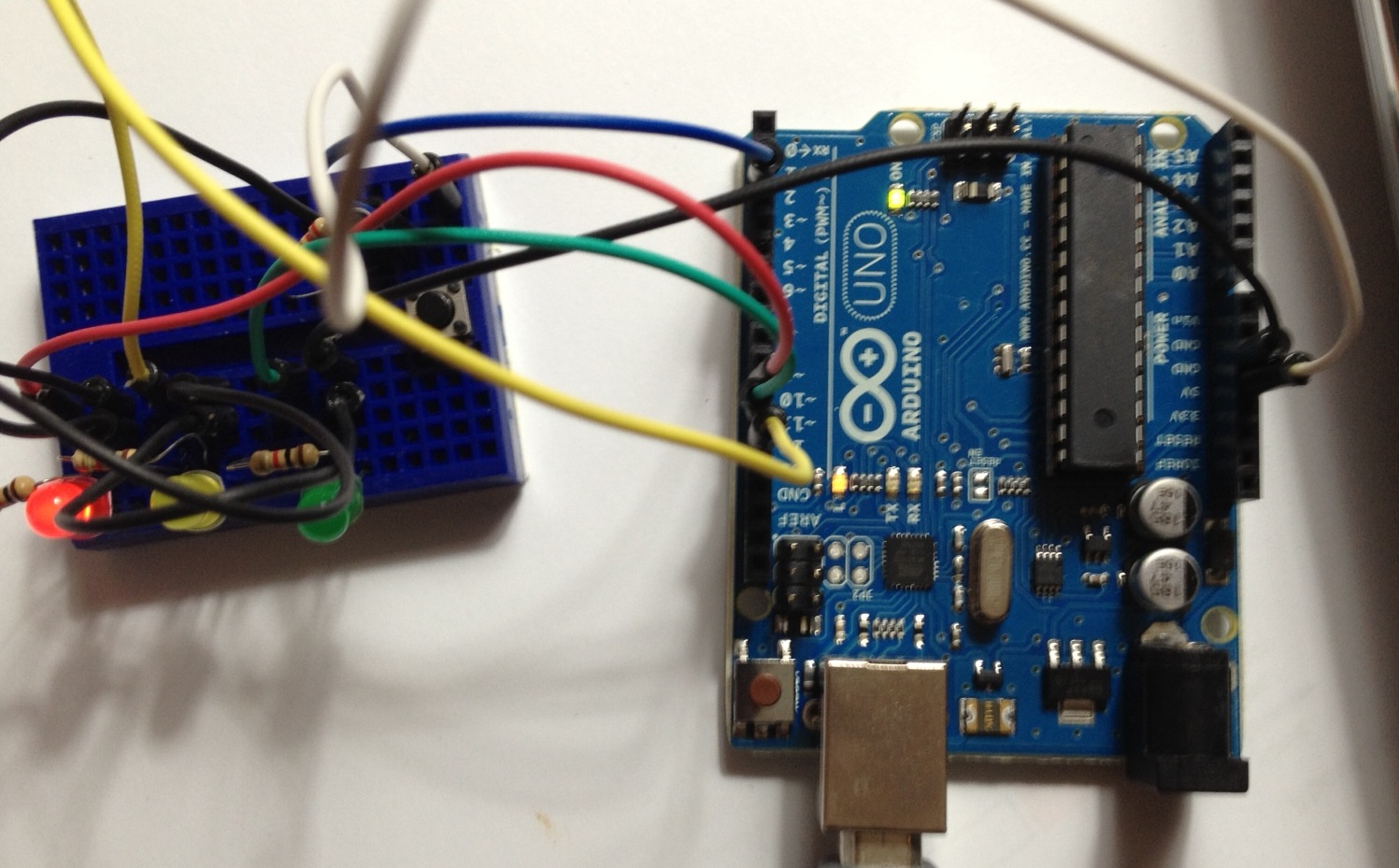
The LEDs were hooked up with resistors on pins 10, 11, 12. The push button was hooked up with a pull down resistor on pin 2 (powered but 5v) and everything was grounded. The wiring setup is shown in the picture below.


I created a github site to store the code for the various experiments. This site is located at this site. For simplicity, you can grab the code by cloning the entire repository using the command:

      git clone git@github.com:mark-r-stevens/Ardadv.git

The code for this example is in Test/Test00. Things I learned with this simple example:
  1. The loop function is called repeatedly so it is possible that the button will be held down and marked as HIGH for many iterations. We only want to change the light on the transition from Released to Pressed. This implies keeping track of the button state and triggering on the event (not the state).
  2. The Serial line needs to be initialized in setup. Flush also needs to be called so that values get output promptly. The println should flush things, but to be safe I added an explicit flush.
  3. I need a bigger breadboard. Something with power rails and more space would have greatly simplified the wiring. Also, these get cluttered pretty quick so using colored wires really helps.
  4. I am getting old. Reading the color coding on these resistors is for the young ;)
  5. Pictures of the layout is challenging. I will need to get a better breadboard and layout the wires so that you can see things a little better in the images.
The next project will begin work on getting accelerometer readings and trying to estimate platform attitude for initial attempts at dead-reckoning. I have also been surfing to find a small robot platform with wheel encoders. 

Review of Beginning Arduino


Beginning Arduino [Paperback]

Michael McRoberts (Author)


http://www.amazon.com/Beginning-Arduino-Michael-McRoberts

The book I ordered on getting started with Arduino arrived yesterday. Grabbed some coffee and read the first 250 pages. The book was clearly written for people  who have not done much breadboard design and not written and compiled c code. That said, the book provides a nice introduction to using the Arduino micro controller, the IDE and working with sensors.

If you have written c or c++ on a regular basis, you should be able to quickly skim a large part of the book. The code examples and projects were easy to follow straight forward. Even if you have written a large amount of code, I would still recommend the book as it will get you in the right mind set for the level of sophisitcation in the code. It will also get you thinking about how to manage pin configurations and connections so that projects can be re-produced.

 There were several things I did not like about the book. There seemed to be a lot of formatting errors (e.g., the columns had the wrong labels, values were split across columns, clear search/replace errors, etc). There were also several examples where 3.1412 was used for PI. Also, the code was not formatted very well making it difficult to parse.

Overall, I think it was a good place to start. Next steps are to write a little code and turn on some lights....

Sunday, February 26, 2012

Getting Started

Probably the best place to get started is with the overall goal. I have worked as a software developer for almost 20 years, specializing in video exploitation. I often deal with all types of optical sensor systems and  associated meta-data. Usually when the data gets to me, it is heavily processed. I decided to learn more about IMU/INS/GPS at the sensor level. A little googling lead me to discover the Arduino boards. This is very appealing since there is a large base of sensors and software to draw from and you can get raw sensor measurements quickly and easily.

I figured I would write this blog as a way of documenting what worked and did not work. In addition, it will give me a place to store all the information gathered in a step by step set of instructions that I can come back to later. So the goal is to learn things and document them. If you find this useful, all the better. If others can correct my mistakes before they get too out of hand that would be greatly appreciated.

I am envisioning three successive projects with the end goal of developing an autonomous robot that builds a map of its environment. The so-called SLAM (simultaneous localization and mapping) problem is something I have done work on in the past so I understand the challenges associated with this undertaking. The projects are:

  1. A small scale 2W robot that fits in the palm of your hand. I am thinking something along the lines of dfrobot-2wd-mobile-platform with an accelerometer, gyroscope, and magnetometer. This project will focus on getting the sensors to work and initial dead reckoning.
  2. A medium scale robot build on a hacked apart roomba. This would add a camera (or perhaps stereo) to estimate 3D structure in the scene. The Arduino does not seem to have the processing power to deal with image processing, so this will probably involve a companion SBC (single board computer) using a PC104 form factor. The roomba battery should be able to support this, time will tell.
  3. A large scale robot using GPS and more powerful motors. This plan is less thought out, but there seems to be several sites discussing use of wheel chair motors.
So the goal is learning (and documenting), the projects are laid out, next step is to start learning. I ordered an introduction to the Arduino on amazon. Seems like the most basic place to start.....